


VLSI Design Articles
Why Chips Fail: A Basic Guide to Chip Defects and IC Failure Analysis
Fun Facts About the Semiconductor Industry
Why Are Semiconductor Chips Expensive? Manufacturing Cost Explained
Instruction Set Architecture: How ISA Shapes Modern Chip Design


Get In Touch For Details! Request More Information
What is RTL Design? A Complete Beginner’s Guide
Jul 21, 2026 6 Min Read 675 Views
(Last Updated)
Table of contents
- TL;DR Summary
- Introduction
- What is RTL Design?
- What is RTL Design in VLSI?
- Why RTL Design Matters in VLSI
- Real-World Use Cases of RTL Design
- Example Scenario
- RTL Design Flow Explained
- Step-by-Step RTL Design Flow
- Where Verilog RTL Fits
- RTL Coding Example
- What Hardware Does This Create?
- RTL vs Gate Level: What’s the Difference?
- Simple Analogy
- Skills Needed to Become an RTL Design Engineer
- Core Technical Skills
- Beginner Roadmap for RTL Design
- Learn Digital Logic
- Start with Verilog RTL
- Build Basic RTL Blocks
- Design FSMs
- Simulate and Debug
- Learn Synthesis and Timing
- Build Projects and Portfolio
- Salary and Career Scope for RTL Design Engineers
- Career Path
- Common Mistakes in RTL Design
- Writing RTL Like Software Code
- Confusing Blocking and Non-Blocking Assignments
- Creating Unintended Latches
- Ignoring Reset Strategy
- Not Checking Waveforms Properly
- Writing Code That Simulates but Does Not Synthesize Well
- Ignoring Timing While Writing RTL
- Wrapping Up
- Frequently Asked Questions
- What is RTL Design?
- What is RTL design in VLSI?
- Is RTL coding the same as programming?
- What is Verilog RTL?
- What is the difference between RTL vs gate level?
- What skills are needed for an RTL design engineer?
- Is RTL Design a good career?
- Can beginners learn RTL Design?
TL;DR Summary
RTL Design is a core step in digital VLSI design where engineers convert a chip’s functional requirements into hardware logic using Verilog RTL, SystemVerilog, or VHDL. It explains how data moves between registers, how logic responds to clocks, and how the design should behave before synthesis. If you want to become an RTL design engineer, focus on digital electronics, RTL coding, finite state machines, timing basics, simulation, synthesis, and verification fundamentals.
Introduction
If AI chips, smartphones, EVs, 5G devices, and data centers are growing fast, one skill quietly sits at the heart of digital chip development: RTL Design. Before a processor or controller becomes silicon, engineers describe its logic using code at the register transfer level.
RTL Design is the process of describing digital hardware behavior using hardware description languages like Verilog or SystemVerilog. It defines how data moves between registers and how logic operations happen on every clock cycle. In VLSI, RTL becomes the bridge between architecture ideas and actual gate-level hardware.
The demand is strong because semiconductor investment is rising globally. SEMI forecasts global semiconductor manufacturing equipment sales to reach $165.9 billion in 2026, up 23.2% year-on-year.
What is RTL Design?
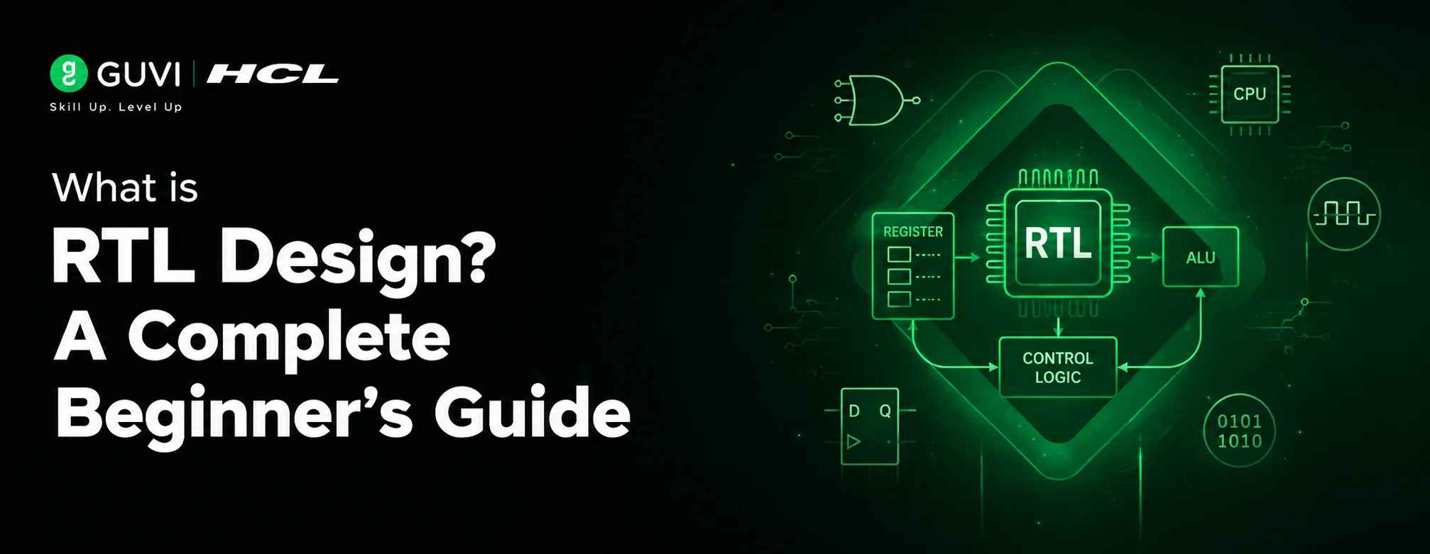
RTL Design stands for Register Transfer Level Design. It is a hardware design method used to describe how data flows between registers and how logic circuits process that data during clock cycles.
In simple terms, RTL is not normal software code. It is code that represents actual hardware. When you write RTL coding in Verilog, you are describing flip-flops, multiplexers, counters, adders, controllers, and state machines that can later be synthesized into gates.
What is RTL Design in VLSI?
RTL design in VLSI is the stage where chip specifications are converted into a functional hardware description. This RTL code is simulated, verified, synthesized, and eventually transformed into a gate-level netlist.
For example, if a company is building a wireless communication chip, the architecture team may define modules like packet processing, encryption, memory control, and signal handling. The RTL design engineer converts those modules into hardware logic.
Also Explore : Why ECE Graduates are Switching to VLSI Careers
India’s semiconductor market was estimated at around $38 billion in 2023, reached about $45–50 billion in 2024–2025, and is expected to reach $100–110 billion by 2030, according to India Semiconductor Mission-related estimates published by PIB.
Why RTL Design Matters in VLSI
RTL Design is important because it decides how efficiently a digital chip performs. A clean RTL design can improve speed, reduce power consumption, simplify verification, and make synthesis smoother.
This is why RTL sits close to the center of the digital chip development lifecycle. A small mistake in RTL coding can later create timing issues, verification failures, or expensive silicon bugs.
Real-World Use Cases of RTL Design
RTL is used across industries where custom digital hardware is needed.
| Industry | RTL Design Use Case |
| Consumer electronics | Mobile processors, camera controllers, display engines |
| Automotive | ADAS chips, battery management logic, infotainment controllers |
| Telecom | 5G baseband processing, routers, network accelerators |
| Data centers | AI accelerators, memory controllers, high-speed interfaces |
| Aerospace and defense | Secure processors, FPGA-based controllers, signal systems |
Example Scenario
Imagine an EV company wants a custom controller for battery monitoring. The RTL design engineer may design logic that reads sensor data, checks safety thresholds, triggers alerts, and communicates with other vehicle systems.
That logic begins as RTL before it becomes real hardware.
RTL Design Flow Explained
The RTL design flow helps teams move from an idea to verified digital hardware. Each stage reduces uncertainty and prepares the design for implementation.
A good RTL design flow also improves teamwork between architecture, design, verification, synthesis, and physical design teams.
Step-by-Step RTL Design Flow
| Step | What Happens |
| Specification | Define what the digital block should do |
| Microarchitecture | Break the design into registers, datapaths, FSMs, and control logic |
| RTL Coding | Write Verilog RTL, SystemVerilog, or VHDL code |
| Simulation | Check whether the RTL behaves correctly |
| Linting | Detect coding issues, unconnected signals, and unsafe constructs |
| Synthesis | Convert RTL into gate-level logic |
| Static Timing Analysis | Check whether timing requirements are met |
| Gate-Level Verification | Compare synthesized design behavior with RTL |
Where Verilog RTL Fits
Verilog RTL is one of the most widely used ways to describe digital logic. It helps engineers model registers, combinational circuits, sequential logic, and finite state machines.
For beginners, Verilog is often the first step because its syntax is simpler than SystemVerilog. However, professional teams often use SystemVerilog for stronger design and verification support.
RTL Coding Example
RTL coding becomes easier when you connect it with actual hardware behavior. Let’s take a simple counter.
module counter (
    input clk,
    input reset,
    output reg [3:0] count
);

always @(posedge clk or posedge reset) begin
    if (reset)
        count <= 4'b0000;
    else
        count <= count + 1;
end

endmodule
This code does not just “run” like software. It describes a 4-bit register that updates on every clock edge.
What Hardware Does This Create?
This Verilog RTL example creates:
- A 4-bit register
- Reset logic
- Increment logic
- Clock-driven sequential behavior
That is the key mindset shift. RTL coding describes circuits, not instructions for a CPU.
RTL vs Gate Level: What’s the Difference?
Many beginners confuse RTL with gate-level design. Both are related, but they represent different abstraction levels in VLSI.
RTL focuses on behavior and data movement. Gate level focuses on actual gates, flip-flops, and netlists after synthesis.
| Factor | RTL Design | Gate-Level Design |
| Abstraction | Higher | Lower |
| Written By | RTL design engineer | Generated mostly by synthesis tools |
| Language | Verilog, SystemVerilog, VHDL | Gate-level netlist |
| Focus | Functionality and register transfers | Actual logic gates and timing |
| Readability | Easier for humans | Harder to read |
| Main Use | Design and simulation | Timing, equivalence, and implementation checks |
Simple Analogy
Think of RTL Design as the blueprint of a house. Gate-level design is closer to the detailed construction layout that shows every brick, wire, and connection.
Both matter, but RTL is where the design intent is first captured.
Skills Needed to Become an RTL Design Engineer
A strong RTL design engineer combines digital logic knowledge with disciplined coding and debugging skills. You do not need to master everything on day one, but you need a clear roadmap.
The best way to learn is to build small digital blocks, simulate them, and gradually move toward processor or communication blocks.
Core Technical Skills
| Skill Area | What to Learn |
| Digital electronics | Gates, flip-flops, counters, multiplexers |
| Verilog RTL | Modules, always blocks, blocking vs non-blocking assignments |
| FSM design | Moore and Mealy state machines |
| Timing basics | Setup time, hold time, clock frequency |
| Simulation | Testbenches, waveform debugging |
| Synthesis basics | Area, timing, power trade-offs |
| Verification basics | Assertions, functional coverage, test scenarios |
Beginner Roadmap for RTL Design
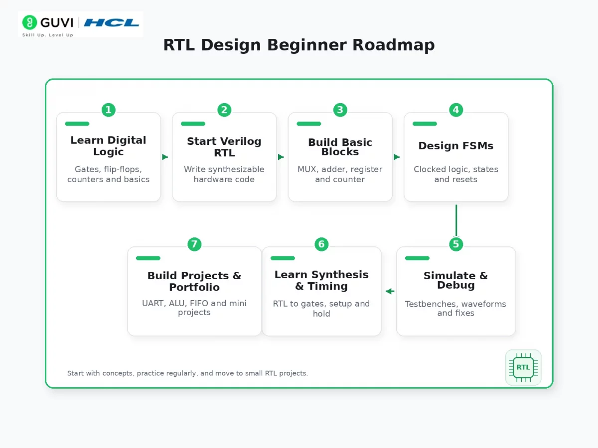
You can learn RTL Design step by step by starting with digital logic, then moving into Verilog RTL, simulation, synthesis, timing, and hands-on projects.
1. Learn Digital Logic
Start with the building blocks of digital hardware: logic gates, flip-flops, multiplexers, counters, registers, and finite state machines.
This foundation helps you understand what your RTL code will eventually become after synthesis. Without digital logic clarity, Verilog RTL can feel like normal programming, which is the wrong mindset.
2. Start with Verilog RTL
Once your basics are clear, begin RTL coding using Verilog or SystemVerilog. Learn modules, ports, wires, registers, always blocks, and assignments.
Focus on writing synthesizable code, not just code that works in simulation. A good RTL design engineer always thinks about the hardware that the code will create.
3. Build Basic RTL Blocks
Practice small blocks before jumping into complex chip-level designs. Start with adders, multiplexers, encoders, decoders, counters, shift registers, and simple ALUs.
These mini blocks help you understand combinational and sequential logic clearly. They also make waveform debugging easier in the early stages.
4. Design FSMs
Finite State Machines, or FSMs, are used to control hardware behavior across multiple clock cycles. You will see them in controllers, protocol logic, memory interfaces, and communication blocks.
Practice both Moore and Mealy FSMs. Also learn how reset, next-state logic, and output logic work together in a clean RTL design.
5. Simulate and Debug
After writing RTL code, test it using a testbench. Simulation helps you verify whether the design behaves correctly before synthesis.

Learn to read waveforms carefully. Most beginner mistakes in RTL coding become visible when you inspect clock edges, reset behavior, signal transitions, and output timing.
6. Learn Synthesis and Timing
Synthesis converts RTL into gate-level logic. This is where your Verilog RTL becomes actual hardware made of gates, flip-flops, and interconnects.
At this stage, learn basic timing concepts like setup time, hold time, clock period, and critical path. These concepts help you write RTL that is not only functionally correct but also implementation-friendly.
7. Build Projects and Portfolio
Once you are comfortable with basic blocks, build small VLSI projects such as UART, SPI controller, FIFO, ALU, traffic light controller, or a simple RISC-V module.
Document each project with the problem statement, RTL code, testbench, waveform screenshots, and what you learned. This portfolio can help you stand out when applying for RTL design engineer roles.
Also read : VLSI Roadmap for Becoming a VLSI Engineer
Salary and Career Scope for RTL Design Engineers
RTL Design is a strong career path because it sits inside the semiconductor, electronics, embedded systems, and chip design ecosystem. The growth of AI hardware, automotive electronics, and India’s semiconductor push makes this field especially relevant.
According to Glassdoor salary data submitted in July 2026, an RTL design engineer in India earns an average of around ₹6.6 LPA, with typical salaries ranging from about ₹4.5 LPA to ₹11.75 LPA and higher earners reaching above ₹23 LPA.
Career Path
| Experience Level | Possible Role |
| 0–2 years | Junior RTL Engineer, VLSI Trainee |
| 2–5 years | RTL Design Engineer, Digital Design Engineer |
| 5–8 years | Senior RTL Engineer, Module Owner |
| 8+ years | SoC Designer, Design Lead, Architect |
The U.S. Bureau of Labor Statistics projects electrical and electronics engineer employment to grow 7% from 2024 to 2034, faster than the average for all occupations, with about 17,500 openings per year.
Common Mistakes in RTL Design
RTL Design becomes easier when you avoid a few beginner traps early. Most mistakes happen when learners write code that simulates correctly but does not translate into clean, reliable hardware.
1. Writing RTL Like Software Code
A common mistake is treating RTL coding like C, Python, or Java programming. In software, code runs line by line, but in RTL Design, your code describes hardware that works in parallel.
Before writing any Verilog RTL block, ask yourself: “What circuit will this create?” This habit helps you think like a hardware designer instead of a software programmer.
2. Confusing Blocking and Non-Blocking Assignments
Beginners often mix = and <= without understanding the hardware impact. As a general practice, blocking assignments are used for combinational logic, while non-blocking assignments are used for clocked sequential logic.
Using the wrong assignment type can create simulation mismatches and hard-to-debug behavior. This is especially risky in counters, FSMs, pipelines, and register-based logic.
3. Creating Unintended Latches
Unintended latches usually happen when all possible conditions are not assigned in combinational logic. For example, missing an else or default case can make the synthesis tool preserve the previous value.
This can lead to unexpected hardware behavior and timing issues. Always assign default values in combinational blocks and cover every branch clearly.
4. Ignoring Reset Strategy
Reset logic decides how your design starts after power-up or during recovery. If reset behavior is unclear, different registers may start in unknown states during simulation or silicon testing.
A good RTL design engineer defines whether the reset is synchronous or asynchronous and applies it consistently. This makes the design easier to verify, synthesize, and debug.
5. Not Checking Waveforms Properly
Many learners stop once the simulation shows the expected output, but they do not inspect the waveform closely. This can hide issues related to clock edges, reset timing, glitches, or delayed signal updates.
Waveform debugging is one of the most important RTL coding skills. You should check how every key signal changes cycle by cycle, not just whether the final output looks correct.
6. Writing Code That Simulates but Does Not Synthesize Well
Some Verilog constructs may work in simulation but may not be suitable for synthesis. This includes delays, poorly controlled loops, incomplete sensitivity lists, or design logic that cannot map cleanly to hardware.
Always write synthesizable RTL if the goal is implementation. Linting tools and synthesis reports can help you catch these issues early.
7. Ignoring Timing While Writing RTL
Beginners often focus only on functional correctness and forget that real hardware must meet timing. Long combinational paths can reduce clock speed and cause timing violations after synthesis.
To avoid this, break complex logic into smaller stages when needed. Understanding setup time, hold time, and critical paths helps you write RTL that is practical for real VLSI implementation.
Wrapping Up
RTL Design is where digital chip ideas become hardware-ready logic. It helps engineers define how data moves between registers, how circuits behave every clock cycle, and how a design moves toward synthesis and silicon. If you want to enter VLSI, start with digital logic, Verilog RTL, FSMs, simulation, and timing basics. The semiconductor industry is expanding, and RTL design engineers will continue to play a key role in building the next generation of chips.
If you are serious about moving from digital electronics basics to job-ready VLSI skills, structured practice can save you months of confusion. You can explore IIT Delhi CEP Certified VLSI Design Career Program to build guided expertise in RTL, chip design workflows, and industry-oriented projects. Plus, get mentored with industrial experts while opening doors to a range of opportunities!
Frequently Asked Questions
1. What is RTL Design?
RTL Design is the process of describing digital hardware at the register transfer level using languages like Verilog or SystemVerilog. It defines how data moves between registers and how logic behaves on clock cycles.
2. What is RTL design in VLSI?
RTL design in VLSI is the stage where chip specifications are converted into synthesizable hardware code. This code is later verified, synthesized, and transformed into gate-level logic.
3. Is RTL coding the same as programming?
No. RTL coding describes hardware circuits, while programming gives instructions to a processor. In RTL, your code becomes registers, gates, multiplexers, and control logic.
4. What is Verilog RTL?
Verilog RTL is Verilog code written at the register transfer level. It is used to model combinational and sequential digital circuits in a synthesizable format.
5. What is the difference between RTL vs gate level?
RTL describes design behavior and data movement at a higher abstraction level. Gate level represents the actual logic gates and flip-flops generated after synthesis.
6. What skills are needed for an RTL design engineer?
You need digital electronics, Verilog/SystemVerilog, FSM design, timing basics, simulation, synthesis understanding, and debugging skills.
7. Is RTL Design a good career?
Yes. RTL Design is a valuable VLSI career path because digital chips are used in AI, EVs, smartphones, telecom, IoT, and data centers.
8. Can beginners learn RTL Design?
Yes. Beginners can start with digital logic, then learn Verilog RTL, build small projects, write testbenches, and slowly move to larger VLSI blocks.
Success Stories












Did you enjoy this article?