CAD vs CAM: Key Differences & Why It Matters in Design and Manufacturing
Oct 10, 2025 4 Min Read 2798 Views
(Last Updated)
CAD and CAM are software systems that play an integral role in the modern design-to-manufacturing process. From engineering and architecture to automotive and aerospace, they help transform ideas into precise products.
CAD stands for Computer-Aided Design, while CAM stands for Computer-Aided Manufacturing.
If you’re new to product design, mechanical engineering, or industrial workflows, you’ve likely come across CAD vs CAM and wondered, “Which is which?” or “Do I need to learn both?”
This blog breaks it down for you on what CAD and CAM mean, how they differ, where they connect, and why understanding both is essential for today’s tech-driven industries.
Table of contents
- What is CAD (Computer-Aided Design)?
- What is CAM?
- Difference between CAD and CAM
- How CAD and CAM Work Together
- CAD vs CAM Learning Path: Which One to Start With and What Each Offers
- Conclusion: Start Where the Process Begins
- FAQs
- What is CAD and CAM?
- Which is better, CAD or CAM?
- Is CAD CAM hard to learn?
- How is CAM different to CAD?
What is CAD (Computer-Aided Design)?
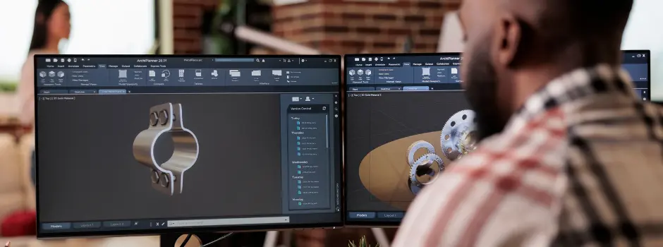
CAD, or Computer-Aided Design, refers to the use of computer software to create, edit, and visualize 2D drawings and 3D models of physical objects. It helps engineers, architects, and designers accurately represent product dimensions, shapes, and technical details before anything is physically made.
The main goal of CAD is to improve precision, reduce manual errors, and allow for quick modifications in the design process. It replaces traditional hand-drafting by providing tools to model complex parts and assemblies digitally.
CAD software is widely used in industries like manufacturing, automotive, aerospace, architecture, and consumer product design. Some popular examples of CAD tools include AutoCAD, SolidWorks, CATIA, and Autodesk Inventor.
Example:
In the automotive industry, CAD is used to design every component of a car from the engine block to the dashboard layout. Engineers use 3D CAD models to simulate how each part fits, moves, and performs under stress before any physical prototype is built. This ensures that the design is both functional and manufacturable, while cutting down on material waste and testing time.
With CAD, teams can collaborate, simulate real-world performance, and make data-driven design decisions, all while saving time and minimizing the need for physical prototypes.
What is CAM?
CAM, or Computer-Aided Manufacturing, refers to the use of computer software to plan, control, and automate the operation of machines involved in the production of physical parts. It converts digital designs, typically created in CAD, into detailed instructions that guide manufacturing equipment such as CNC machines, lathes, mills, and routers.
The primary function of CAM is to generate precise toolpaths and motion sequences, allowing machines to cut, shape, or assemble materials with high accuracy. By automating these instructions, CAM reduces manual programming, speeds up production, minimizes human error, and ensures consistency in output.
CAM is commonly used in industries like automotive, aerospace, electronics, and metal fabrication. Software like Siemens NX, SolidCAM, and PowerMILL is widely adopted to manage machining processes, simulate operations, and improve workflow efficiency on the shop floor.
Example:
Imagine an automotive company needs to produce a custom aluminum gearbox housing. After the design team creates a 3D model in CAD software, the CAM system uses that model to calculate the most efficient cutting paths for the CNC machine. It then generates instructions that guide the machine through roughing, drilling, and finishing processes, ensuring that the final part matches design specifications with minimal material waste.
While CAD defines what a part should look like, CAM determines how it gets made, bridging the gap between digital design and physical production.
Difference between CAD and CAM
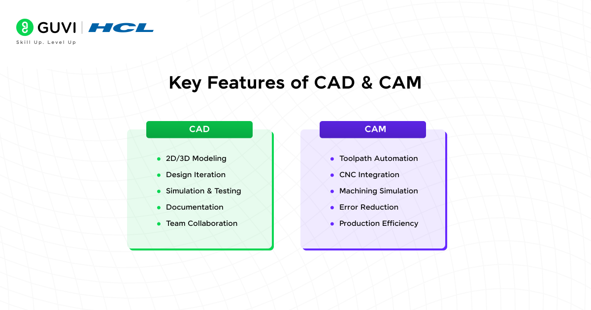
| Aspect | CAD (Computer-Aided Design) | CAM (Computer-Aided Manufacturing) |
| Purpose | Used to design 2D drawings and 3D models of physical products | Used to control machines and automate the manufacturing process |
| Primary Function | Creates the digital representation of a product | Converts digital models into toolpaths and machine instructions |
| Users | Engineers, architects, and product designers | Machinists, CNC programmers, manufacturing engineers |
| Output | Design files, blueprints, 3D models | G-code, toolpaths, machine-ready instructions |
| Software Examples | AutoCAD, SolidWorks, CATIA, Autodesk Inventor | Siemens NX, SolidCAM, Mastercam, PowerMILL |
| Process Role | Starts the workflow, defines what the part should look like | Follows CAD, defines how the part will be made |
| Automation Level | Semi-automated, relies on human design input | Highly automated, especially in generating machining paths |
| Integration | Often integrated with CAM for seamless design-to-manufacture workflows | Receives input from CAD to begin manufacturing |
| Example | Designing a bicycle frame using SolidWorks | Using CAM software to mill the frame from aluminum on a CNC machine |
If you are a civil engineering fresher looking to strengthen your design skills, HCL GUVI’s Civil CAD Course helps you master AutoCAD Civil 3D, Revit, and structural drafting. Learn through real-world construction projects and get placement support to confidently step into the civil design and infrastructure industry.
How CAD and CAM Work Together
Let’s say a bicycle manufacturing company wants to launch a new lightweight road bike frame.
Step 1: Concept and Design (CAD)
The design team starts with SolidWorks to model the bike frame. They define geometry, weight distribution, material thickness, and dimensions based on performance and safety standards. The 3D model helps visualize how the frame will look, fit with other components like wheels and gears, and withstand stress during use. Multiple design iterations are made, all without creating a physical prototype.
Step 2: Simulation and Validation (Still CAD)
Before production begins, the same CAD software is used to simulate stress points, load-bearing capacity, and aerodynamics. Changes are made digitally to improve performance and reduce material use.
Step 3: Transition to Manufacturing (CAM)
Once the design is finalized, the CAD file is exported into a CAM system, like Siemens NX or SolidCAM. The CAM software reads the geometry and generates detailed toolpaths for a CNC machine, dictating how and where to cut, drill, and shape each section of the aluminum tubing that forms the frame.
Step 4: Machining and Production (CAM in action)
CNC machines follow the CAM-generated instructions to cut the tubing with millimeter-level precision. The frame is machined, finished, and checked for tolerances, exactly as designed in the CAD model.
In this workflow, CAD defines what needs to be made, while CAM determines how to make it. They work in sequence, inside the same organization, turning an idea into a final, physical product.
CAD vs CAM Learning Path: Which One to Start With and What Each Offers
| Criteria | CAD (Computer-Aided Design) | CAM (Computer-Aided Manufacturing) |
| Who Should Learn It | Students or professionals interested in product design, modeling, architecture, or prototyping | Individuals focused on machining, tool operations, or physical product manufacturing |
| Learning Priority | Recommended as the starting point—CAD comes before CAM in the design-to-production pipeline | Learn after CAD if you’re moving into CNC programming or production-focused roles |
| Key Features for Learners | Offers design freedom, visual validation, and multiple design iterations without added cost | Automates G-code generation, simulates manufacturing, and improves material usage efficiency |
| Limitations | Doesn’t cover actual manufacturing; limited to design intent and visual output | Depends heavily on CAD input; limited without upstream design data |
| Skills Developed | Spatial reasoning, geometry understanding, visualization, and design documentation | Toolpath planning, machine setup knowledge, production strategy, material removal logic |
| Learning Curve | Medium, requires understanding of technical drawing standards, design logic, and modeling tools | High, requires familiarity with machining processes, machine capabilities, and post-processing |
| Hardware Requirements | Can be run on mid-level laptops; mainly GPU and RAM dependent | Often needs high-performance machines for simulation, especially with 5-axis or high-resolution parts |
| Career Roles Supported | CAD Designer, Product Design Engineer, Mechanical Draftsman, BIM Specialist | CAM Programmer, CNC Operator, Manufacturing Engineer, Tooling Engineer |
| Tool Compatibility | Output formats (.DWG, .STEP, .IGES) are fed directly into CAM platforms for machining | Reads CAD file formats and converts them into G-code for execution on manufacturing equipment |
| Industry Demand | High in automotive, architecture, aerospace, consumer product design, and R&D | High in precision manufacturing, aerospace components, metal fabrication, and tooling industries |
| Why You Should Learn It | Builds a foundation for engineering design, helps visualize before build, required in most design roles | Bridges the gap between design and production, reduces human error, and supports automated manufacturing |
| Where It’s Used Most | Product development, mechanical component design, civil structure modeling, architecture planning | CNC workshops, industrial machine shops, die/mold creation, additive and subtractive manufacturing |
If you are a mechanical engineering graduate aiming to build job-ready CAD skills, HCL GUVI’s Mechanical CAD Course offers hands-on training in AutoCAD, SolidWorks, CATIA, and Ansys. Work on real projects, build your portfolio, and receive expert mentorship with placement support to boost your core career path. Explore now!
Conclusion: Start Where the Process Begins
CAD and CAM are not competing choices. They are connected steps in the design-to-manufacturing journey. CAD helps you think, plan, and visualize. CAM helps you build, produce, and deliver. One creates the blueprint. The other brings it to life.
For beginners, learning CAD is the natural starting point. It builds your ability to design with precision, solve problems visually, and communicate ideas through models and drawings. Once that foundation is strong, learning CAM makes more sense. It gives you control over how your designs are made on the shop floor.
If you’re aiming for a career in mechanical, civil, or product design, knowing where to begin and how to scale your skills can define your success.
Start with clarity. Build with confidence. Grow into the roles that shape real-world innovation.
FAQs
1. What is CAD and CAM?
CAD stands for Computer-Aided Design, used for creating digital drawings and 3D models. CAM stands for Computer-Aided Manufacturing, used to convert those models into machine-driven production instructions.
2. Which is better, CAD or CAM?
Both CAD and CAM serve different purposes. CAD is for designing models; CAM is for manufacturing them. Most industries require both to streamline product development and improve production efficiency.
3. Is CAD CAM hard to learn?
CAD and CAM have learning curves, but with structured training and practice, they’re manageable. CAD is often easier to start with, while CAM requires an understanding of machining and tooling.
4. How is CAM different to CAD?
CAD focuses on designing the part digitally, while CAM handles how that part is produced using machines. CAD defines form and structure; CAM defines movement, tools, and manufacturing actions.









Did you enjoy this article?