


Database Articles
SQL Window Functions: Practical Examples Every Analyst Needs
Microservices vs Monolith: Making the Right Architectural Choice


Get In Touch For Details! Request More Information

How to Design ER Diagram for a Hospital Management System : Complete Beginner’s Guide
Jul 20, 2026 5 Min Read 1339 Views
(Last Updated)
If you are learning database design, one of the most practical projects you will work on is an ER diagram for a hospital management system. It covers almost every concept you need to know: entities, attributes, relationships, primary keys, foreign keys, and cardinality. It also mirrors how real hospital software is built, which makes it valuable for both exams and actual development.
This guide walks you through everything from scratch. What an ER diagram is, what symbols are used, which entities to include, what attributes each entity has, how they all connect, and how to read the relationships correctly.
Quick Answer
An ER diagram for a hospital management system is a visual blueprint of the hospital database. It maps out entities like Patient, Doctor, Appointment, Room, Department, Bill, and Medical Record, shows the attributes each one holds, and defines how they relate to each other using cardinality rules like one-to-many and many-to-many.
Table of contents
- What Is an ER Diagram
- ER Diagram Symbols You Must Know
- What Is a Hospital Management System
- Step-by-Step: How to Design an ER Diagram for a Hospital Management System
- Core Entities in an ER Diagram for a Hospital Management System
- Patient
- Doctor
- Department
- Appointment
- Room
- Medical Record
- Bill
- Nurse
- Lab Report
- Relationships in an ER Diagram for a Hospital Management System
- Cardinality Explained Simply
- Primary Key vs Foreign Key
- Tools to Draw an ER Diagram for a Hospital Management System
- Tips for Beginners Designing an ER Diagram for a Hospital Management System
- 💡 Did You Know?
- Conclusion
- FAQs
- What is an ER diagram for a hospital management system?
- What are the main entities in an ER diagram for a hospital management system?
- What is cardinality in an ER diagram for a hospital management system?
- How is a many-to-many relationship handled in an ER diagram for a hospital management system?
- Which free tools can I use to draw an ER diagram for a hospital management system?
What Is an ER Diagram
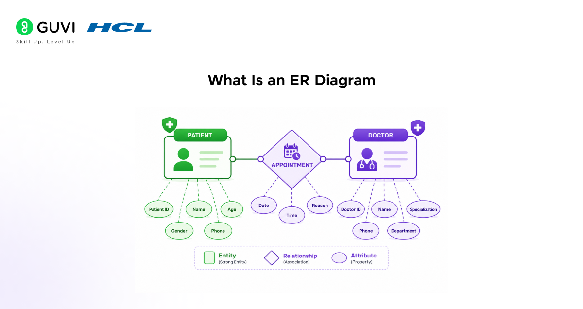
An ER diagram stands for Entity-Relationship diagram. It is a visual tool used to design and plan the structure of a database before you start writing any code or creating tables.
What an ER diagram shows:
- Entities: The main objects or things in the system (like Patient, Doctor, Room)
- Attributes: The details or properties that describe each entity (like name, age, ID)
- Relationships: How two entities are connected or interact with each other
- Cardinality: How many of one entity relates to how many of another
Why ER diagrams are important:
- They help you plan the database before building it
- They prevent missing important data fields
- They make it easy for developers, designers, and managers to understand the system together
- They directly translate into database tables when the project moves to implementation
Learn database design, SQL, normalization, ER modeling, relational database concepts, queries, joins, constraints, indexing, and real-world data management skills with HCL GUVI’s Database Course. This beginner-friendly program helps you understand how systems like hospital management software store and organize data efficiently, making it perfect for aspiring developers, backend engineers, and database professionals preparing for projects and technical interviews.
ER Diagram Symbols You Must Know
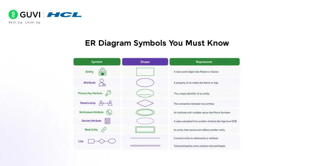
Before designing an ER diagram for a hospital management system, you need to understand the standard symbols used.
| Symbol | Shape | Represents |
| Entity | Rectangle | A real-world object like Patient or Doctor |
| Attribute | Oval or Ellipse | A property of an entity like Name or Age |
| Primary Key Attribute | Underlined oval | The unique identifier of an entity |
| Relationship | Diamond | The connection between two entities |
| Multivalued Attribute | Double oval | An attribute with multiple values like Phone Numbers |
| Derived Attribute | Dashed oval | A value calculated from another attribute like Age from DOB |
| Weak Entity | Double rectangle | An entity that cannot exist without another entity |
| Line | Single line | Connects entity to relationship or attribute |
| Double line | Double line | Total participation, every instance must participate |
What Is a Hospital Management System
A hospital management system (HMS) is software that manages all hospital operations digitally. It replaces paper records and manual tracking with organized, connected digital data.
Core modules in a hospital management system:
- Patient Management: Registering patients, storing demographics and medical history
- Doctor Management: Tracking doctor details, specializations, and schedules
- Appointment Management: Booking, rescheduling, and tracking consultations
- Room and Ward Management: Allocating and tracking room availability
- Department Management: Organizing hospital departments and assigned staff
- Billing and Payments: Generating bills and recording payment history
- Medical Records: Storing diagnoses, prescriptions, lab reports, and treatment history
- Pharmacy and Medication: Managing medicines prescribed and dispensed
An ER diagram for a hospital management system captures all of these modules through connected entities.
Step-by-Step: How to Design an ER Diagram for a Hospital Management System
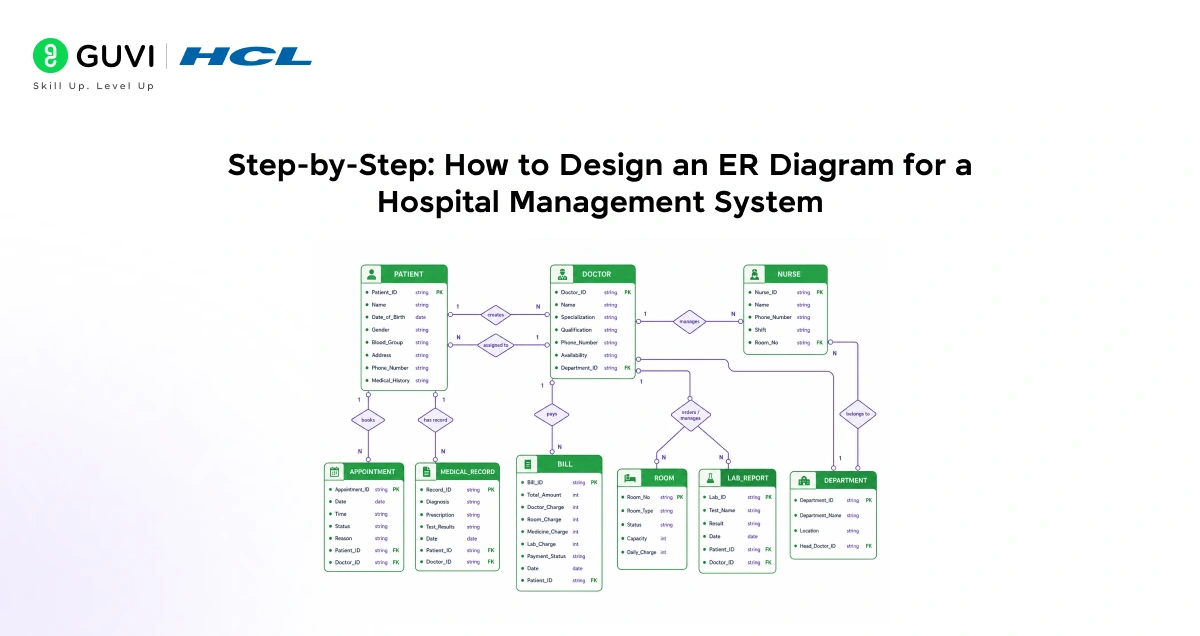
Follow these steps every time you design an ER diagram for a hospital management system. This is the standard approach used in both exams and real projects.
Step 1: Identify all entities List every major object that the system needs to track.
Step 2: Identify attributes for each entity For each entity, list all the data fields it needs. Mark the primary key.
Step 3: Identify relationships between entities Determine how each entity connects to others using action verbs like consults, belongs to, pays, and assigns.
Step 4: Determine cardinality For each relationship, decide if it is one-to-one, one-to-many, or many-to-many.
Step 5: Draw the diagram Place entities as rectangles, connect them with diamond-shaped relationship labels, and attach oval-shaped attributes.
Step 6: Review for completeness Check that every entity has a primary key, every relationship has a cardinality, and no important data field is missing.
Core Entities in an ER Diagram for a Hospital Management System
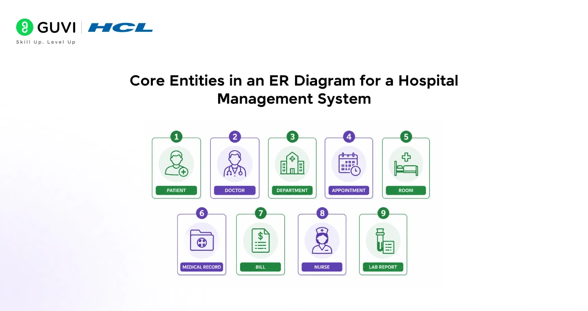
1. Patient
The Patient entity is the most central entity in any ER diagram for a hospital management system. Every other entity connects back to the patient in some way.
Attributes:
| Attribute | Type | Notes |
| Patient_ID | Primary Key | Unique identifier for each patient |
| Name | String | Full name of the patient |
| Date_of_Birth | Date | Used to derive age |
| Age | Derived Attribute | Calculated from Date_of_Birth |
| Gender | String | Male, Female, Other |
| Blood_Group | String | A+, B+, O+ etc. |
| Address | String | Residential address |
| Phone_Number | Multivalued | Patient may have multiple contacts |
| Medical_History | String | Previous conditions and surgeries |
2. Doctor
The Doctor entity stores all information about medical practitioners in the hospital.
Attributes:
| Attribute | Type | Notes |
| Doctor_ID | Primary Key | Unique identifier for each doctor |
| Name | String | Full name |
| Specialization | String | Cardiology, Neurology, Pediatrics etc. |
| Qualification | String | MBBS, MD, MS etc. |
| Phone_Number | Multivalued | Doctor may have multiple contacts |
| Availability | String | Days and time slots available |
| Department_ID | Foreign Key | Links doctor to their department |
3. Department
The Department entity organizes the hospital into functional units.
Attributes:
| Attribute | Type | Notes |
| Department_ID | Primary Key | Unique identifier for each department |
| Department_Name | String | Cardiology, Radiology, Orthopedics etc. |
| Location | String | Floor or block in the hospital |
| Head_Doctor_ID | Foreign Key | The doctor who leads the department |
4. Appointment
The Appointment entity is a relationship-turned-entity (also called an associative entity) because it holds data about the interaction between a Patient and a Doctor.
Attributes:
| Attribute | Type | Notes |
| Appointment_ID | Primary Key | Unique identifier for each appointment |
| Date | Date | Date of the appointment |
| Time | Time | Time slot booked |
| Status | String | Scheduled, Completed, Cancelled |
| Patient_ID | Foreign Key | Links to Patient |
| Doctor_ID | Foreign Key | Links to Doctor |
| Reason | String | Brief reason for the visit |
5. Room
The Room entity manages the physical spaces patients are admitted to.
Attributes:
| Attribute | Type | Notes |
| Room_No | Primary Key | Unique room identifier |
| Room_Type | String | General, ICU, Private, Semi-Private |
| Status | String | Available, Occupied |
| Capacity | Integer | Number of beds in the room |
| Daily_Charge | Integer | Per day cost of the room |
6. Medical Record
The Medical Record entity stores the clinical history of each patient visit.
Attributes:
| Attribute | Type | Notes |
| Record_ID | Primary Key | Unique identifier for the record |
| Diagnosis | String | Doctor’s diagnosis |
| Prescription | String | Medicines prescribed |
| Test_Results | String | Lab or imaging results |
| Date | Date | Date of the record entry |
| Patient_ID | Foreign Key | Links to Patient |
| Doctor_ID | Foreign Key | The doctor who created the record |
7. Bill
The Bill entity tracks all financial transactions in the hospital.
Attributes:
| Attribute | Type | Notes |
| Bill_ID | Primary Key | Unique bill number |
| Patient_ID | Foreign Key | Links to Patient |
| Total_Amount | Integer | Total charges |
| Doctor_Charge | Integer | Consultation fee |
| Room_Charge | Integer | Room rental charges |
| Medicine_Charge | Integer | Pharmacy charges |
| Lab_Charge | Integer | Diagnostic test charges |
| Payment_Status | String | Paid, Pending, Partially Paid |
| Date | Date | Date of bill generation |
8. Nurse
The Nurse entity tracks nursing staff assigned to patients and wards.
Attributes:
| Attribute | Type | Notes |
| Nurse_ID | Primary Key | Unique identifier |
| Name | String | Full name |
| Phone_Number | String | Contact number |
| Shift | String | Morning, Evening, Night |
| Room_No | Foreign Key | The room the nurse manages |
9. Lab Report
The Lab Report entity stores all diagnostic test information.
Attributes:
| Attribute | Type | Notes |
| Lab_ID | Primary Key | Unique test identifier |
| Patient_ID | Foreign Key | Links to Patient |
| Doctor_ID | Foreign Key | Doctor who ordered the test |
| Test_Name | String | Blood test, MRI, X-Ray etc. |
| Result | String | Test findings |
| Date | Date | Date the test was conducted |
Relationships in an ER Diagram for a Hospital Management System
| Relationship | Entities Involved | Cardinality | Meaning |
| Consults | Patient, Doctor | Many-to-Many | A patient can consult many doctors. A doctor can treat many patients. |
| Books | Patient, Appointment | One-to-Many | One patient can have many appointments. |
| Has | Doctor, Appointment | One-to-Many | One doctor can have many appointments. |
| Belongs To | Doctor, Department | Many-to-One | Many doctors belong to one department. |
| Assigned To | Patient, Room | Many-to-One | Many patients can be assigned to a room over time. |
| Manages | Nurse, Room | One-to-Many | One nurse can manage multiple rooms. |
| Pays | Patient, Bill | One-to-Many | One patient can have many bills. |
| Has Record | Patient, Medical Record | One-to-Many | One patient can have many medical records. |
| Orders | Doctor, Lab Report | One-to-Many | One doctor can order many lab reports. |
| Undergoes | Patient, Lab Report | One-to-Many | One patient can undergo many lab tests. |

Cardinality Explained Simply
Cardinality tells you how many instances of one entity can relate to instances of another entity.
| Cardinality Type | What It Means | Hospital Example |
| One-to-One (1:1) | One record in Entity A matches exactly one record in Entity B | One patient has one unique Patient_ID |
| One-to-Many (1:N) | One record in Entity A matches many records in Entity B | One doctor has many appointments |
| Many-to-Many (M:N) | Many records in Entity A match many records in Entity B | Many patients consult many doctors |
How many-to-many relationships are handled:
A many-to-many relationship cannot be directly stored in a database. It is broken down using an intermediate entity called an associative entity or junction table. For example, the many-to-many relationship between Patient and Doctor is handled through the Appointment entity which holds Patient_ID and Doctor_ID as foreign keys.
Primary Key vs Foreign Key
These two concepts are essential for understanding any ER diagram for a hospital management system.
| Term | Definition | Example |
| Primary Key | A unique identifier for each record in an entity. No two records can have the same value. | Patient_ID in the Patient table |
| Foreign Key | A field in one entity that points to the primary key of another entity. It creates the link between two entities. | Patient_ID inside the Appointment table pointing to the Patient table |
Tools to Draw an ER Diagram for a Hospital Management System
You do not need to draw by hand. Several free tools make it easy:
| Tool | Type | Best For |
| draw.io (diagrams.net) | Free, browser-based | Quick, clean ER diagrams |
| Lucidchart | Free tier available | Collaborative team design |
| dbdiagram.io | Free, code-based | Developers who prefer typing |
| MySQL Workbench | Free, desktop | Direct database design and export |
| ERDPlus | Free, browser-based | Students and academic projects |
Tips for Beginners Designing an ER Diagram for a Hospital Management System
- Start with entities before attributes. List all the main objects first. Do not get lost in attribute details before you have the full entity list.
- Every entity must have a primary key. No exceptions. The primary key uniquely identifies each record and is the backbone of all relationships.
- Break every many-to-many into an associative entity. If you find a many-to-many relationship, always create an intermediate entity to handle it properly.
- Use foreign keys to create links. Every relationship between two entities is implemented in the database using a foreign key in one of the tables.
- Do not add attributes that can be derived. Age can be calculated from Date_of_Birth. Store Date_of_Birth and mark Age as a derived attribute rather than storing both.
- Name relationships with action verbs. Consults, pays, assigns, belongs to. Verb-based names make the diagram easy to read and understand.
- Review from a real hospital perspective. Ask yourself: if a patient comes in today, what data does the hospital need to capture? That thinking helps you avoid missing entities.
💡 Did You Know?
- The concept of ER diagrams was introduced by Peter Chen in 1976 in his landmark research paper and has been the standard method for database design ever since.
- In a real hospital management system, the ER diagram for a hospital management system can have over 50 entities once modules like pharmacy, HR, insurance, and emergency care are included.
Conclusion
An ER diagram for a hospital management system is one of the best learning projects in database design because it touches every core concept: entities, attributes, primary keys, foreign keys, one-to-many relationships, many-to-many relationships, and associative entities. Once you can design this diagram cleanly, you are ready to tackle any real-world database project.
Start by drawing just four entities: Patient, Doctor, Appointment, and Bill. Connect them with the relationships from this guide. Then add Department, Room, Medical Record, and Lab Report one at a time. Each addition teaches you something new. By the time all nine entities are on your diagram, you will have practiced every concept that database design exams and interviews test.
FAQs
1. What is an ER diagram for a hospital management system?
An ER diagram for a hospital management system is a visual representation of the hospital database. It shows all the main entities like Patient, Doctor, and Appointment, the attributes each entity holds, and how they connect to each other through defined relationships and cardinality rules.
2. What are the main entities in an ER diagram for a hospital management system?
The main entities are Patient, Doctor, Department, Appointment, Room, Medical Record, Bill, Nurse, and Lab Report. Each entity represents a key module in the hospital’s operations and connects to other entities through relationships like consults, pays, belongs to, and assigns.
3. What is cardinality in an ER diagram for a hospital management system?
Cardinality defines how many instances of one entity relate to instances of another. In the ER diagram for a hospital management system, one patient can have many appointments (one-to-many), many patients can consult many doctors (many-to-many), and one bill belongs to one patient (one-to-one in some designs).
4. How is a many-to-many relationship handled in an ER diagram for a hospital management system?
A many-to-many relationship cannot be stored directly in a database. It is resolved using an associative entity or junction table. For example, the many-to-many relationship between Patient and Doctor is converted into two one-to-many relationships using the Appointment entity, which holds Patient_ID and Doctor_ID as foreign keys.
5. Which free tools can I use to draw an ER diagram for a hospital management system?
The most popular free tools are draw.io (also called diagrams.net), Lucidchart (free tier), dbdiagram.io, MySQL Workbench, and ERDPlus. For beginners, draw.io is the easiest to start with because it is browser-based, requires no installation, and has built-in ER diagram shapes.
Success Stories

About the Author
Jebasta
I translate the language of data into stories that anyone can understand. As a writer with a data science background, I simplify analytics, AI, and decision-making so beginners and enthusiasts can confidently explore the world of data.
View all posts by Jebasta
Connect with me @
















Did you enjoy this article?