


Mechanical CAD Articles
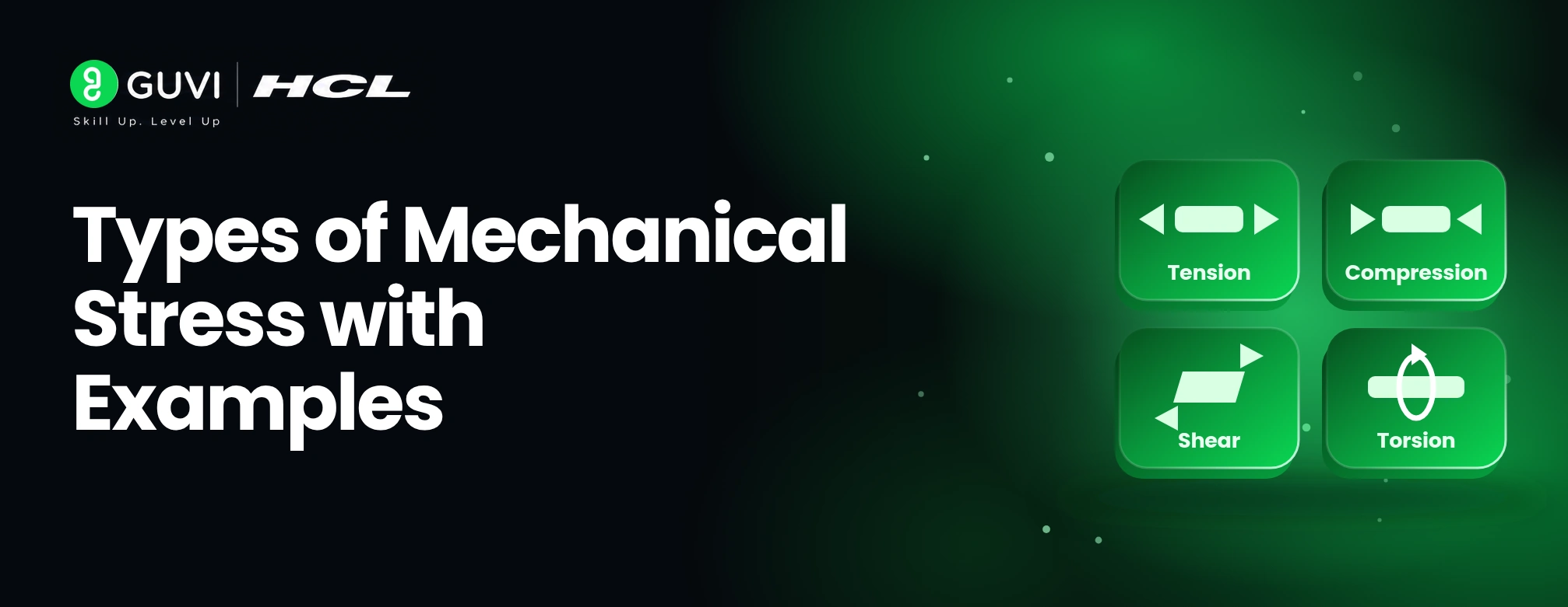
Types of Mechanical Stress with Examples
LinkedIn Profile Tips for Mechanical Engineers: How to Build a Recruiter-Friendly Profile


Get In Touch For Details! Request More Information
Stress and Strain in Mechanical Engineering: Types, Formulas and Applications
Nov 05, 2026 5 Min Read 22 Views
(Last Updated)
Every machine part, from a crankshaft to a bicycle frame, carries loads. Whether it survives depends on how its material responds to those loads, and that is what stress and strain describe. Stress tells you how intensely a load is acting inside the material, while strain tells you how much the material deforms in response. Together, they form the backbone of strength of materials and help engineers choose materials, size components, and keep designs safe.
This guide covers the meaning, types, formulas, and relationship of stress and strain, along with where they are used in real mechanical design.
Table of contents
- TL;DR
- What Is Stress in Mechanical Engineering?
- Strengthen Your Mechanical Engineering Skills with HCL GUVI
- Types of Stress
- Tensile Stress
- Compressive Stress
- Shear Stress
- Bending Stress
- Torsional Stress
- What Is Strain in Mechanical Engineering?
- Types of Strain
- Strengthen Your Mechanical Engineering Skills with HCL GUVI
- Relationship Between Stress and Strain
- The Stress-Strain Curve
- Difference Between Stress and Strain
- Applications of Stress and Strain in Mechanical Engineering
- Importance of Understanding Stress and Strain
- Strengthen Your Mechanical Engineering Skills with HCL GUVI
- Conclusion
- Frequently Asked Questions (FAQs)
- What are stress and strain in mechanical engineering?
- What is the difference between stress and strain?
- What are the main types of stress?
- What is Hooke's Law?
- Why are stress and strain important in mechanical design?
TL;DR
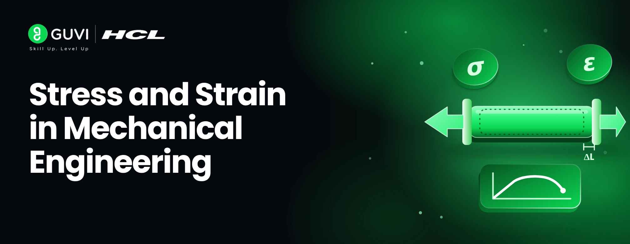
- Stress is the internal resisting force per unit area (σ = F/A, unit: Pa). Strain is deformation relative to original size (ε = ΔL/L₀, dimensionless).
- The main types of stress are tensile, compressive, shear, bending, and torsional. Strain types include tensile, compressive, shear, volumetric, and lateral.
- Within the linear elastic region, Hooke’s Law links them: σ = Eε.
- The stress-strain curve shows how a material moves from elastic behaviour to yielding, ultimate strength, and fracture.
- Engineers use these concepts for shafts, gears, pressure vessels, springs, frames, and aerospace parts.
What Is Stress in Mechanical Engineering?
Stress is the internal resisting force developed per unit area inside a material when an external load acts on it.
For a member under a uniform axial load:
σ = F / A
- σ = stress (Pa or N/m²; MPa is more common in practice)
- F = applied force (N)
- A = cross-sectional area (m²)
Stress rises with force and falls as area increases. That is why a thicker rod carries the same load more comfortably than a thin one.
Example: A steel rod of 10 mm diameter carries an axial pull of 15 kN.
- Area: A = π/4 × (0.01)² = 7.854 × 10⁻⁵ m²
- Stress: σ = 15,000 / 7.854 × 10⁻⁵ ≈ 191 × 10⁶ Pa ≈ 191 MPa
If you double the diameter, the area becomes four times larger and the stress drops to roughly 48 MPa.
Strengthen Your Mechanical Engineering Skills with HCL GUVI
Build a strong foundation in mechanical engineering and design with practical, industry-relevant skills. Explore HCL GUVI’s Mechanical CAD course to gain hands-on experience with CAD software, understand real-world engineering applications, and develop the technical skills needed to advance your mechanical design career.
Types of Stress
Tensile Stress
Develops when a member is pulled or stretched, as in a lifting chain or a tie rod. Formula: σ = F/A.
Compressive Stress
Develops when a member is pushed or squeezed, as in a column or an engine connecting rod during the power stroke. Formula: σ = F/A. This holds for short, stocky members. Long, slender members may buckle before the material itself fails, so buckling must be checked separately.
Shear Stress
Develops when forces act parallel to a cross-section and try to slide one part over another, as in a bolt, rivet, or pin joint.
τ = V / A
Here V is the shear force and A is the area resisting it. This gives the average shear stress. The actual distribution is not perfectly uniform, so treat it as a simplified estimate.
Bending Stress
Develops when a bending moment acts on a component such as an axle or a beam. One side stretches (tension) and the other compresses.
σ = M·y / I
M is the bending moment, y is the distance from the neutral axis, and I is the second moment of area. This formula assumes a straight beam, linear elastic material, and small deflections. The maximum stress occurs at the outermost fibre.
Torsional Stress
Develops when a twisting moment (torque) acts on a component such as a drive shaft.
τ = T·r / J
T is the torque, r is the radial distance from the axis, and J is the polar moment of area (for a solid circular shaft, J = πd⁴/32). This applies to circular shafts of uniform cross-section within the elastic range. Non-circular sections need different treatment.
Also checkout: Engineering Mechanics: Fundamentals of Force and Motion
What Is Strain in Mechanical Engineering?
Strain is the measure of deformation of a material relative to its original dimension. It can describe a change in length, shape, or volume.
For normal strain:
ε = ΔL / L₀
- ε = normal strain
- ΔL = change in length
- L₀ = original length
Strain is a ratio of two lengths, so it is dimensionless. It is often written as a decimal, a percentage, or in microstrain (με).
Example: A 500 mm metal rod stretches by 0.25 mm under tension.
ε = 0.25 / 500 = 0.0005, or 0.05% (500 microstrain).
Types of Strain
- Tensile strain: Increase in length per unit original length under a pulling force, as in a stretched bolt.
- Compressive strain: Decrease in length per unit original length under a pushing force, as in a loaded column. It is commonly treated as negative.
- Shear strain (γ): Angular distortion caused by shear stress. For small angles, γ ≈ δ/h (in radians), where δ is the sideways displacement over height h. A rubber mounting under a sideways load is a good example.
- Volumetric strain: Change in volume relative to original volume: ε_v = ΔV / V₀. It matters in hydrostatically loaded parts such as pressurised components.
- Lateral strain: Change in a transverse dimension under axial load: ε_lat = Δd / d₀. A rod pulled in tension gets longer and slightly thinner. The ratio of lateral to axial strain gives Poisson’s ratio, ν = −ε_lat / ε_axial.
Strengthen Your Mechanical Engineering Skills with HCL GUVI
Build a strong foundation in mechanical engineering and design with practical, industry-relevant skills. Explore HCL GUVI’s Mechanical CAD course to gain hands-on experience with CAD software, understand real-world engineering applications, and develop the technical skills needed to advance your mechanical design career.
Relationship Between Stress and Strain
When a load is applied, stress develops inside the material and strain shows up as deformation. For many materials at low loads, the two are proportional. This is Hooke’s Law:
σ = E·ε
- σ = normal stress
- E = Young’s modulus (modulus of elasticity), a measure of stiffness
- ε = normal strain
Hooke’s Law holds only within the linear elastic region, and only for materials and loading conditions that behave linearly. Typical values are about 200 GPa for steel and about 70 GPa for aluminium alloys. For shear, the equivalent relation is τ = Gγ, where G is the shear modulus.
Using the earlier rod: 191 MPa in steel (E ≈ 200 GPa) gives ε ≈ 0.00095, so a 1 m rod would stretch by about 0.95 mm.

Also checkout: Newton’s Laws of Motion for Mechanical Engineers: Concepts, Formulas and Applications
The Stress-Strain Curve
A tensile test on a ductile metal such as mild steel produces a curve with these key stages:
- Proportional limit: The end of the straight-line region where σ and ε are directly proportional.
- Elastic limit: The maximum stress from which the material still returns fully to its original shape. It lies very close to the proportional limit for many metals.
- Yield point / yield strength: The stress at which noticeable plastic deformation begins. Many materials have no sharp yield point, so a 0.2% offset method is used to define it.
- Plastic deformation: Permanent deformation that remains after the load is removed.
- Ultimate tensile strength (UTS): The maximum engineering stress the material can carry. After this, necking begins in ductile metals.
- Fracture point: The stress and strain at which the specimen breaks.
Elastic vs plastic deformation: A spring that returns to its length after a light load shows elastic deformation. A paper clip bent past its limit stays bent, which shows plastic deformation.
Also checkout: Friction in Mechanical Systems: Types, Formulas, and Applications
Difference Between Stress and Strain
Stress measures the intensity of internal force, while strain measures relative deformation. Do not confuse either with strength (the stress a material can withstand) or stiffness (its resistance to deformation, represented by E).
| Aspect | Stress | Strain |
| Definition | Internal resisting force per unit area | Deformation per unit original dimension |
| Cause | External load or torque | Stress acting on the material (or temperature change) |
| Formula | σ = F/A | ε = ΔL/L₀ |
| SI unit | Pascal (Pa or N/m²) | Dimensionless |
| Physical meaning | How intensely the material is loaded | How much the material has deformed |
| Example | Tensile stress in a connecting rod | Elongation of a bolt during tightening |
Applications of Stress and Strain in Mechanical Engineering
- Automobile components: Crankshafts, axles, and suspension parts face combined bending, torsion, and fluctuating loads. Stress analysis guides their size and material.
- Shafts and gears: Shafts are checked for torsional and bending stress. Gear teeth are checked for bending stress at the root and contact stress at the surface.
- Pressure vessels: Internal pressure creates hoop and longitudinal stress. For a thin-walled cylinder, hoop stress is σ = pr/t and longitudinal stress is pr/2t (valid when the wall is thin compared to the radius).
- Springs: Designers relate load to deflection and check the shear stress in the wire to make sure the spring returns to its original length.
- Machine frames: Frames are checked for both stress (will it fail?) and strain or deflection (will it bend too much for accurate operation?).
- Aerospace components: Parts must be strong and light, so engineers study material behaviour under varying loads, using stress and strain data to avoid over- or under-design.
- Structural components: Beams, trusses, and supports are assessed for deformation and load-bearing capacity.
In all these cases, stress and strain calculations drive material selection (is the yield strength high enough?), component sizing (how thick should it be?), and reliability (is there an adequate safety margin?).
Also checkout: What is Mechanical Engineering 101: Introduction to Principles, Applications and Skills
Importance of Understanding Stress and Strain
A solid grasp of these concepts helps mechanical engineers to:
- Select suitable materials for each application.
- Predict how much a part will deform under load.
- Prevent failure by keeping working stress below yield or fatigue limits.
- Determine safe operating loads.
- Improve component design by removing excess material where stress is low and reinforcing where it is high.
- Evaluate strength, stiffness, and durability together.
- Support product safety and reliability.
Strengthen Your Mechanical Engineering Skills with HCL GUVI
Build a strong foundation in mechanical engineering and design with practical, industry-relevant skills. Explore HCL GUVI’s Mechanical CAD course to gain hands-on experience with CAD software, understand real-world engineering applications, and develop the technical skills needed to advance your mechanical design career.
Conclusion
Stress and strain describe two sides of the same story: stress is the internal intensity of the load, and strain is the resulting deformation. Hooke’s Law connects them within the elastic range, and the stress-strain curve shows what happens beyond it, through yielding, strengthening, and fracture. Whether you are sizing a shaft, checking a pressure vessel, or choosing between steel and aluminium, understanding stress and strain is what turns a rough design into a safe and efficient one. Master the formulas, respect their assumptions, and practise with real components.
Frequently Asked Questions (FAQs)
1. What are stress and strain in mechanical engineering?
Stress is the internal resisting force per unit area in a loaded material (σ = F/A). Strain is the deformation relative to the original dimension (ε = ΔL/L₀).
2. What is the difference between stress and strain?
Stress measures how intensely a material is loaded and is expressed in pascals. Strain measures how much the material deforms and is dimensionless.
3. What are the main types of stress?
The main types are tensile, compressive, shear, bending, and torsional stress.
4. What is Hooke’s Law?
Hooke’s Law states that stress is proportional to strain (σ = Eε) within the linear elastic region, where E is Young’s modulus. It does not apply beyond that region.
5. Why are stress and strain important in mechanical design?
They help engineers choose materials, size components, predict deformation, and keep working stresses within safe limits so that parts do not fail.
Success Stories

About the Author
Vishalini Devarajan
An Aerospace Engineer turned content writer, I focus on making complex concepts easy to understand through well-structured, reader-friendly blogs. Whether it’s a technical topic or a non-technical one, I love creating content that is clear, engaging, and impactful.
View all posts by Vishalini Devarajan
Connect with me @










Did you enjoy this article?